. Introduction
Over the last two decades, we have seen a rapid development of satellite and space technologies. Satellites of new navigation systems have been launched in space: BeiDou system (BDS), Galileo, Quasi-Zenith Satellite System (QZSS), Indian Regional Navigational Satellite System (IRNSS). The existing Global Positioning System (GPS) and Globalnaja Navigacionnaja Sputnikova Sistema (GLONASS) system have been modernised, mainly through the replacement of navigation satellites with new-generation systems that offer new signals and services. Currently, we have four coexisting, independent Global Navigation Satellite Systems (GNSS). These include: American GPS, Russian GLONASS, Chinese BDS and European Galileo system. In addition, GNSS comprises two regional navigation systems, the Japanese system QZSS, which complements GPS, and the IRNSS. IRNSS, also known under the operational name NAVIC (NAVigation with Indian Constellation), is an autonomous regional satellite navigation system that provides services of accurate positioning and time measurement in real time. GNSS is complemented by the satellite-based augmentation system (SBAS), which creates regional networks of terrestrial satellite systems that enhance the accuracy and reliability of positioning over large areas. They are of key importance for aviation, maritime and land navigation, and they are also widely used in the geospatial industry, geodetic or cartographic works. Positioning based on several GNSS protects the user against a complete loss of positioning in the event of a single system failure. Furthermore, a simultaneous use of many frequencies allows to eliminate ionospheric errors, which, in turn, is a basic condition that enables to achieve precise positioning accuracy. Thus, the current state of development of satellite navigation systems allows us to access six different positioning systems (Table 1), which together provide access to over 140 observation satellites operating in different orbits. Assuming that each satellite transmits observation signals on several frequencies (three on average), we can use multiple measurement frequencies simultaneously and then select the optimal solution.
Table 1
List of GNSS satellites (QZSS, 2021)
Due to widespread availability of the GNSS satellite technology, it has found application in many fields. Obviously, depending on the purpose of the measurements, a different level of their accuracy is required. Hence, a number of works have been devoted to determining the optimal solution, allowing to obtain the expected precision and accuracy of measurements. When we discuss the use of this technology for the implementation of surface deformation monitoring, we can refer to the work of Baryła and Paziewski (2012), in which the authors present main assumptions of the concept of ground deformation monitoring based on GPS satellite measurements, or to the work of Hastaoglu (2016), in which the results of radar measurements InSAR and GNSS for the monitoring of landslide movements were compared. Among other works which address the problem of optimisation of observation networks for the acquisition of high observation accuracy of surface deformation, the works of Stepniak et al. (2013), Blachowski et al. (2010) and Sokoła-Szewioła and Siejka (2009) can be referenced. The problem of quality assessment involving the geometry of the GNSS observation network for monitoring surface deformation, in this case in the area of a dam, was discussed in detail by Sanjaya et al. (2019), where the authors defined the most optimal solutions, taking into account the criteria of precision and reliability of measurements.
Since it is now possible to obtain measurement results with increasingly higher precision, satellite observations can also be applied in the case of natural disasters, including seismic hazards. GNSS have become one of the most effective ways to monitor temporary movements of the earth’s crust, using high-frequency (1 and 10 Hz) satellite observations. Appropriately positioned satellite receivers can directly observe displacements, which makes GNSS especially valuable in the event of large earthquakes (Avallone et al., 2011; Larson et al., 2003). High-precision satellite orbit and clock products in real time have become available, and they significantly expand the application of real-time GNSS deformation monitoring when combined with other seismic systems. The work of Bock et al. (2011) offers a solution based on the combination of data from the GPS – fast accelerometers collocated stations, thus obtaining time series of displacements with several millimetre-level accuracy. Noteworthy is the precise point positioning (PPP) algorithm presented in Song et al. (2016), which improves the dynamic precision of PPP. The algorithm was validated on the basis of GNSS observation data, including data from International GNSS Service (IGS) tracking stations, data from a simulated earthquake experiment and measured seismic data. As we can infer from the above, the issue involving the validation of the accuracy and precision of the applied GNSS monitoring solution, depending on the purpose of its implementation, is a priority.
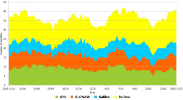
Monitoring of surface movements is also very important in post-mining areas, especially during mine closures. During or after flooding of mines, mechanical properties of the rock mass may be impaired, and it may lead to subsidence, surface landslides, uplift, sinkholes or seismic activity. The above issues are the subject of research carried out under the project ‘Induced earthquake and rock mass movements in coal post mining areas: mechanisms, hazard and risk assessment’ (PostMinQuake). One of its objectives is to examine and select update methods and plans for long-term monitoring of post-mining sites to mitigate the risk of seismic and surface deformation during and after mine closures. The research assumed the implementation of continuous automated monitoring of surface movements using the GNSS in the area of the closed mine ‘Kazimierz-Juliusz’, located in Poland, in the northeastern part of the Upper Silesian Coal Basin. In order to obtain the results of displacement measurements with the accuracy level of several millimetres, an assessment of the accuracy and precision of multi-GNSS observations made in real time was carried out, the results of which are presented in the article. For the purposes of this project, the research was carried out with the use of four global navigation systems (GPS, GLONASS, Galileo, BeiDou) due to the fact that QZSS and IRNSS, being regional systems, are dedicated for specific areas of the globe. However, these areas are significantly distant from the place of the research, and on this basis, it was concluded that presently, these systems are unsuitable for their effective use in the investigated area. For these reasons, the work focuses on the use of four GNSS in four different variants. Variant I consisted in using a single GPS in the measurements. Variant II was implemented based on the use of GPS and GLONASS. In variant III, three navigation systems were used: GPS, GLONASS and Galileo. Variant IV was implemented based on the simultaneous use of observations from four GNSS. The applied approach made it possible to conduct tests with a different number of navigation systems. Figure 1 shows an example illustrating how the total number of satellites available to the observer changed during the day at the site of conducted research. In addition, the plot shows how the number of available satellites changed throughout the day for individual navigation systems: GPS, GLONASS, Galileo and BeiDou. Based on the above, we conclude that the use of only a single navigation system, for example, GPS, provides us with the access to about eight to nine satellites a day. Also, the possibility of using four GNSS simultaneously increases the average number of available satellites to over 30, and in certain time windows, this number may exceed 40 satellites (Figure 1).
We should also allow for the fact that with the use of many multi-GNSS (Dawidowicz, 2015; Prochniewicz et al., 2016; Ma et al., 2020; Siejka, 2015) the number of available satellites increases, and so does the number of observation signals (Table 2). Each new observation signal should be treated as an additional observation that may potentially have a direct impact on the quality of the performed measurements. As presented in Table 2, only four observed satellites, each belonging to a different navigation system, GPS, GLONASS, Galileo, BeiDou, are able to deliver a total of 15 different observation signals at the same moment of time. Each such signal, in line with the theory of adjustment calculus, should be treated as a potential pseudo-observation that will be used in the adjustment process to precisely determine the ultimate coordinates of the measured point. Thus, the use of many GNSS in measurements is advisable both in terms of a practical and theoretical approach to the issue of using satellite techniques in precise geodetic measurements. A larger number of available satellites ensures better availability and positioning reliability for users. Also, based on the adopted general mathematical model of the solution, it can be concluded that a larger number of correctly realised and accepted for adjustment surplus observations (pseudo-observations) improves the quality of the obtained final results (coordinates).
Table 2
Observation signals used by the receiver Trimble R10 model 2.
. Materials and methods
Test research – general concept
Over the past 25 years, GNSS in civil applications has evolved from a system that in the initial phase was only a system for supporting measurements, mainly surveying grids or control and measurement networks, to a multifunctional, interactive measurement system. Real-time kinematic positioning has become a standard technology in the surveying and cartography sectors. The Real-Time Kinematic (RTK) measurement method is one of the differential techniques that make use of phase shift corrections of GNSS to determine precise near-real-time coordinates. Currently, On-The-Fly (OTF) initialisation is generally used in real-time measurements, where the uncertainty value of phase measurements is quickly determined by the Kalman filtration method or the LAMBDA method. The initiation time of measurements in the GNSS receiver with the application of these methods is on average several to several dozen seconds. As a result, using a single receiver, it has become possible to use real-time high-frequency positioning with centimetre-level accuracy or higher over the entire globe and in its immediate vicinity. Thus, this technology can be used to implement monitoring for various purposes, including continuous monitoring of surface movements in post-mining areas. Test measurements using the RTK method were carried out in view of their application reasonability based on the simultaneous use of several positioning systems. In addition, the research was aimed at determining the degree of compatibility of individual GNSS. Four new-generation satellite receivers, Trimble R10, model 2, were used in the measurements, which are multi-system and multi-channel (672 channels) geodetic satellite receivers adapted to receive and process navigation signals from all currently available GNSS (GPS, GLONASS, BeiDou, Galileo, QZSS, SBAS). Empirical research was performed in a stationary mode on a special test base using the RTK technique, based on corrections from a single reference station.
The coordinates of reference points had been determined earlier independently on the basis of postprocessing of daily static observations. The research consisted in multiple determination of the coordinates of the same reference points, independently, using four different GNSS combinations (Table 3).
Table 3
Basic information on the conducted test measurements.
| Variant | GNSS | Assumed number of measurements in the session | Actual number of performed measurements | Total number of performed measurements | |||
|---|---|---|---|---|---|---|---|
| GPS | GLN* | GAL** | BDS*** | ||||
| I | Yes | - | - | - | ~8640 | ~8594 | ~34,448 |
| II | Yes | Yes | - | - | ~8640 | ~8605 | |
| III | Yes | Yes | Yes | - | ~8640 | ~8625 | |
| IV | Yes | Yes | Yes | Yes | ~8640 | ~8624 | |
During the conducted research, it was possible to obtain over 99.7% of all obtainable observations. High efficiency of the obtained test measurement results from good location of the measurement base and from the reliability of the applied measuring equipment. Basic satellite conditions of the observation site are characterised in Table 4. It presents (a posteriori) the characteristic conditions described by the number of actually observed satellites and the spatial coefficient of geometric accuracy Position Dilution of Precision (PDOP) for the time interval in which the research was carried out.
Table 4
Summary of characteristic satellite conditions during test measurements
The validation of the accuracy of the measurement system based on the GNSS platform for the realisation of continuous automated monitoring of surface movements in post-mining areas, as part of the project carried out, was performed on the basis of the accuracy analysis of the determined coordinates, comprising absolute errors, relative (apparent) errors and mean square errors of a single measurement.
Determination of absolute errors
For the obtained test results, the absolute errors of the coordinates (Δx, Δy, ΔH), measured using the RTK technique, independently for each of the four test measurements, were calculated as the difference of the measured coordinates (xp) and the ’true – catalogue’ coordinates (xk) of the control point. Catalogue coordinates of control points were determined earlier on the basis of two 6-h measurement sessions realised with the use of static GNSS method. Processing of measurement results was performed in a network solution using Trimble Business Center software version 5.51 (TBC v5.51).
where i = 1, . . . , n – number of measurement.Determination of relative errors
In order to determine relative (apparent) errors, systematic errors were eliminated from the obtained measurement results using the classic approach which reads that the arithmetic mean from a long measurement series (n = 8640) accurately approximates the true value. In this way, the systematic errors for the individual, determined coordinates (δx, δy, δH) were calculated, respectively:
As it is commonly known, each measurement is burdened with a systematic error, regardless of the fact whether we have performed one measurement or the entire measurement series. The source of systematic errors lies primarily in the imperfection of measuring instruments and in the used measurement method. Such errors act one-sidedly and add up, and therefore, even minor errors of this type should be carefully eliminated from the measurements.
The relative errors of the measured coordinates (vx, vy, vH) were calculated as follows:
Relative errors occur in all measurement results, and therefore, when performing multiple measurements of the same quantity, we obtain values that differ from each other. The reasons for the occurrence of relative errors are generally not exactly known. They differ in magnitude and sign, and their statistical distribution should be normal.
Calculation of mean square errors of a single measurement
The mean square errors of a single measurement for 24 series – an hour-long independent time series of observations of the coordinates x, y, H, – were calculated according to Equations (10–12):
where i = 1, 2, 3,. . . , n stands for a consecutive number of measurement in each analysed time series.. Results and discussion
Absolute errors
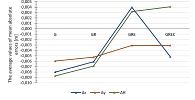
At the first stage of the analysis, absolute errors of the determined coordinates (Δx, Δy, ΔH) were calculated for the obtained test results using Equations (1–3). The mean values of the determined absolute errors for 24 one-hour measurement series, based on various GNSS combinations, are presented in Tables 5 and 6. The average values of mean absolute errors listed in Tables 5 and 6 are presented in Figure 2.
Table 5
Summary of mean absolute errors for the solutions: GPS and GPS + GLONASS.
Table 6
Summary of mean absolute errors for the solutions: GPS + GLONASS + Galileo and GPS + GLONASS + Galileo + BDS.
Based on Tables 5 and 6 and Figure 2, the following conclusions can be drawn:
The average absolute error of the determined northern coordinate (x) in subsequent solutions was as follows:
The average absolute error of the determined eastern coordinate (y) in subsequent solutions was as follows:
The average absolute error of the determined height (H) in subsequent solutions was as follows:
The calculation results of the absolute errors of the determined positions show that the lowest values of errors for all components (x, y, H) were obtained for the solution based on three navigation systems (GPS + GLONASS + Galileo). It should also be noted that for the northern coordinate (x) and for the height (H) in the three-system solution (variant III), the character of absolute errors changed from negative to positive values. Additionally, the absolute values of these errors reached a minimum for all coordinates (x, y, H).
Relative errors
The determined systematic errors are presented in Table 7. The obtained results indicate that by adding the third Galileo constellation (variant III) to the GPS + GLN solution, the values of systematic errors are reduced significantly for all coordinates, and additionally, for the northern coordinate (x) and height (H), their values are changed from negative to positive.
Table 7
List of determined systematic errors
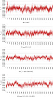
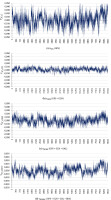
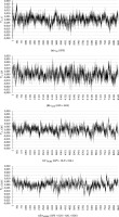
The distribution of the determined relative errors (vx, vy, vH) for the individual coordinates (x, y, H) in the tested measurement variants G, GR, GRE and GREC is presented in the graphs shown in Figures 3–5. The said graphs are characterised by some periodic variation over time, which corresponds to approximately 1 h.
Figure 3
Distribution of relative errors of the northern coordinate (x) for different multi-GNSS solutions
Mean square errors of a single measurement
The calculated mean square errors of a single measurement for 24 one-hour independent time series of the observation for x, y, H coordinates are presented in Tables 8 and 9.
Table 8
List of random errors for variants I and II.
Table 9
List of random errors for variants III and IV.
The analysis of the data contained in Table 8 showed that for the northern coordinate (x), the average random error of a single measurement, which was made with the use of a single GPS, equalled ±4.9 mm. However, with the GLONASS system added, this error increased to ±5.9 mm. When the third Galileo system was added (Table 9), the error was reduced to ±4.4 mm, and with the simultaneous use of four GNSS, the error further decreased to ±4.2 mm (Table 9).
The analysis of the eastern coordinate (y) indicated that the average random error of a single measurement, which was made with the use of a single GPS, was also ±4.9 mm. However, after adding the GLONASS system, the error was reduced to ±4.0 mm. When we added another third Galileo system to the observation setup, the error was reduced to ±3.3 mm. And with the simultaneous use of four GNSS, the error slightly increased to ±3.5 mm.
For the height H, the tests showed that the average random error of a single measurement, which was made with the use of a single GPS, was ±13.7 mm. However, with the GLONASS system added, the error decreased to ± 10.8 mm. When another third Galileo system (Table 9) was added to the observation setup, the error was reduced to ±7.9 mm. With the simultaneous use of four GNSS, it turned out that the error increased to ±8.9 mm (Table 9).
. Conclusions
The use of additional GNSS in real-time kinematic measurements considerably improves satellite conditions of the observation site. The research has demonstrated that, first of all, the average number of satellites observed per day increases significantly, because, as presented in Table 4, with the use of only a single GPS navigation system, we can effectively observe up to eight navigation satellites on average. However, when we have the option of using two systems GPS and GLONASS, the average number of satellites observed increases to 14. With the simultaneous use of three systems GPS, GLONASS and Galileo, the average number of observed satellites amounts to 21. Yet, if we use four GNSS simultaneously (GPS, GLONASS, Galileo, BeiDou), the average number of satellites observed per day will rise to 25. Such an approach makes it possible to increase the availability and efficiency of GNSS measurements, especially in difficult satellite conditions.
By increasing the number of satellites observed at the same time, especially when it is done by the application of additional constellations, we significantly improve satellite conditions of the observation site, which are routinely defined by Dilution of Precision (DOP) parameters. In general, the values of the spatial geometric accuracy factor (PDOP) (Table 4) decrease with the increasing number of constellations used, which bespeaks of better configuration of the satellites in relation to the station being determined.
The use of additional GNSS in RTK measurements has a direct impact on the accuracy of the determined coordinates. The presented results of empirical studies (Tables 8 and 9) have demonstrated a general principle that the mean random error of a single measurement decreases with the addition of an additional GNSS to the observation system. In the light of the obtained research results, such a principle can be accepted for the GPS, GLONASS and Galileo systems. It was also confirmed by the results of the analysis of absolute and relative errors obtained in the study. The inclusion of the Chinese BeiDou satellite constellation in real-time observation for the location covered by the research is not justified at this stage. The conducted research has demonstrated that this constellation does not substantially improve the measurement results, and it even deteriorates them slightly at some time intervals. This may be due to the fact that these systems are not yet fully integrated in terms of equipment for conducting continuous measurements in real time. In this case, adding observations from an additional constellation may only prolong the positioning process by ineffective use of the computing power of the field computer which performs the process of continuous real-time positioning.
It should be accepted that in the case of a planned long-term continuous monitoring of surface deformation using GNSS, it is most desirable to conduct accuracy tests of the measurement system.


